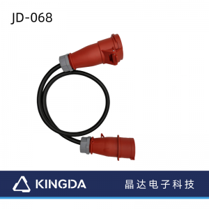
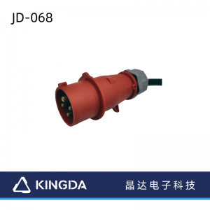
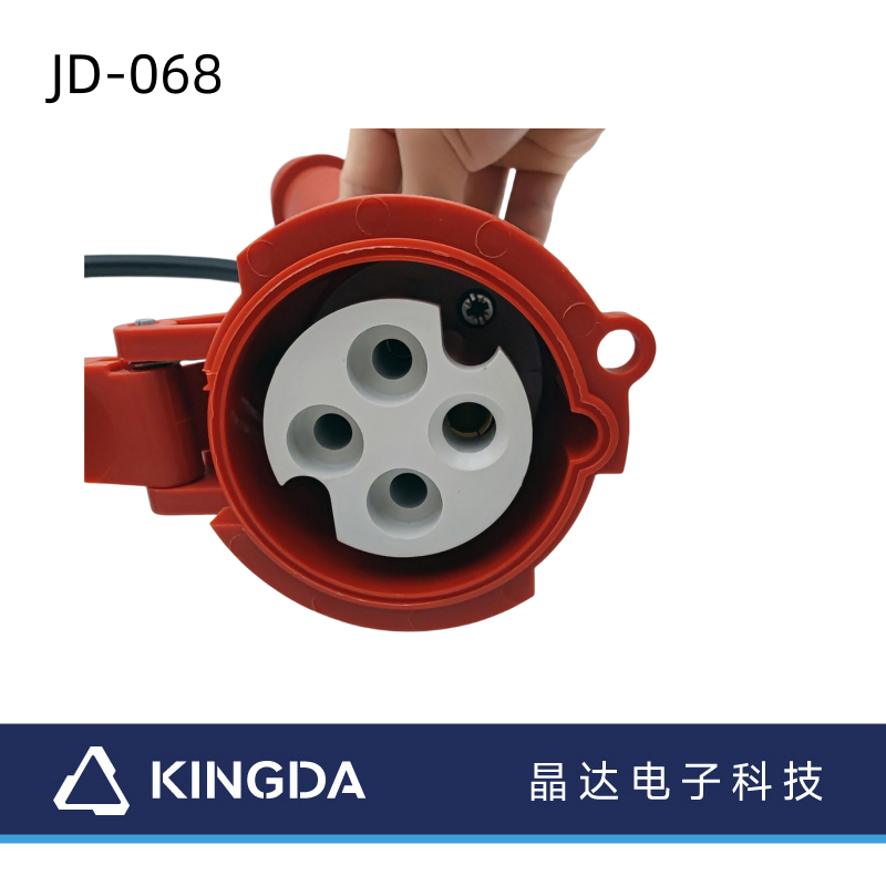
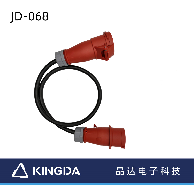
544 European standard waterproof industrial cable 16A three-phase 4-hole IP67ab
Applications:
Features:
This product is widely used in industry, agriculture, airports, docks, ships, metallurgical power plants, construction, railway, water conservancy and other outdoor places
Wide Compatibility:
Typical applications include industrial field, etc.,
Product Detail Specifications
Physical Characteristics
Cable Length
Color Black
Connector Style Straight
Product Weight
Wire Diameter
Packaging Information Package Quantity 1Shipping (Package) Weight
Product Description
Product Detail Specifications
Warranty Information
Part number JD-DC068
Warranty 1 Year
Hardware TYP-252 Waterproof industrial plug to socket cable
Cable Jacket Type ,
Cable Conductor
Connector Material Gold plated
Connector(s)
Connector A TYP-252 Waterproof industrial plug
Connector B TYP-252 Waterproof industrial socket
Specifications
Physical Characteristics
Cable Length
Color Black
Connector Style Straight
Product Weight
Wire Diameter
Packaging Information Package Quantity 1Shipping (Package)
Weight
Maximum Digital transfers at rates
Product Description
TYP-252 Waterproof industrial plug to socket cable
Specifications:
1 Host/controller connection: TYP-252 Waterproof industrial plug/Socket
2, Fire protection: VW-1
3.RoHS compliant
| Electrical | |
| Quality Control system | Operation according to regulation & rules in ISO9001 |
| Insulation Resistance | 1000M min |
| Contact Resistance | 5 ohm max |
| Working Temperature | -25C—80C |
| Data transfer rate |
Introduction of the LVDS interface of the TFT-LCD LCD screen
The LVDS Interface Definition
The LVDS interface definition refers to the LVDS input end interface pin function on the LCD panel side, which can generally be learned through consulting the original factory data of the LCD screen (often called the screen specification book). Although different English standards of LCD screen interface function are different, But it’s not hard to see that, judging by the order of its key letters and numbers, For example, a certain CLAA170EA02 model LCD screen, Look at the interface definition table given by the manufacturer, As can be seen from a short column in English, With RXO and RXE, Each channel has the number “0″ ~ “3″ group data signal, And has 1 set of clock signals (RXOC or RXEC), This shows that the LCD screen is a 30-pin, dual, 8-bit screen, It’s also not hard to see its pin function, That is, “RXO0-” represents the first set of data 1-, “RXO0 +” means the first set of data: 1 +; “RXE0-” indicates the second set of data 1-, “RXE0 +” indicates the second set of data 1 +, The rest, and so on. The LVDS interface features LVDS is a short English “Low Voltage Differential Signaling” that means the low-pressure differential signal. LVDS overcomes the disadvantages of transmitting broadband high power consumption and EMI electromagnetic interference in the TTL level mode, and is a digital video signal transmission mode. The LVDS output interface uses a very low voltage swing (about 350mV) to transmit the data by difference on two PCB wires or a pair of balance cables. The LVDS interface transmits the signal on a differential PCB or balance cable at a rate of hundreds of megbits per second. Due to the low voltage and low current drive mode, it has the advantages of low noise and low power consumption. In LCD color TV, LVDS line uses balance cable mostly, it is twisted pair line actually. The LVDS interface circuit component LCD color TV or color display on the first decoding of the input signals (such as TV, AV, etc.), to obtain the RGB signal, its processing process is basically the same as the ordinary color TV, and then through the RGB-LVDS conversion, output LVDS signal, sent to the LCD screen. Since the TFT in the LCD screen only recognizes the TTL (RGB) signal, the LVDS sent to the LCD screen needs to decoding the TTL signal. It can be seen that the LVDS interface circuit includes two parts: the LVDS output interface circuit on the motherboard side (LVDS transmitter), and the LVDS input interface circuit (LVDS receiver) on the LCD panel side. The LVDS transmitting terminal converts the TTL signal into the LVDS signal, and then transmits the signal to the LVDS decoding IC on the LCD panel side through the row cable or flexible cable between the drive panel and the LCD panel), converting the serial signal into a parallel signal of the TTL level, and then sending it to the LCD timing control and ranks drive circuit.


